jormungand.net »
projects »
robots
curl
⋅
lgr
⋅
devilcat2
⋅
nemo
⋅
tiggerbot2
⋅
logo
⋅
crunch
⋅
devilcat
⋅
tiggerbot
Devilcat
Intro
Devilcat was my second robot, built over the summer of 2002. Following
TiggerBot it was an extremely ambitious project. Devilcat, in two words, could be described as misguided overengineering. Devilcat was a differential-drive robot 18" in diameter weighing in around 50 lbs. Devilcat is named in honor of a theoretical adversary described by one of my computer science professors: a villain that always feeds your algorithms byzantine input that results in worst-case complexity. (This is also pretty much the same as what any real-world robot does.)
Mechanical
Devilcat's main structure was constructed from 1/2" cold-rolled steel square tube. In some sense, learning how to operate a MIG welder was really the only useful outcome from the whole project. This is me working on the frame. It was about 95F out that day, so there was a bit of a tradeoff between wearing heavy clothes and sweating like a dog or not wearing heavy clothes and burning yourself with slag and ultra-violet radiation. In hindsight welding is not the best way to assemble a robot if it can be avoided.
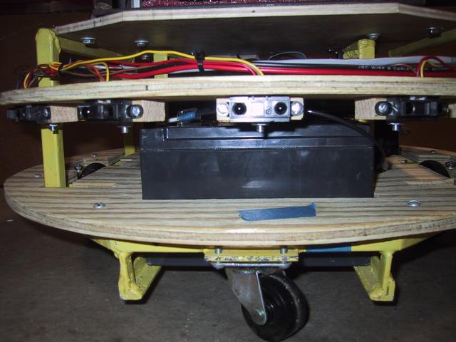
This is a view of the bottom. The drive wheels are hard rubber inline-skate wheels; there are also front and back casters. The reader familiar with geometry will note that a four wheeled vehicle with no suspension works extremely well, but only on perfectly flat surfaces.
Side view of platform showing drive belt. The two motors are large Pittman motors with built in encoders.
Electrical
View showing the batteries, which are two 12V 12Ah sealed-lead-acid batteries wired in series. They provided plenty of electricity to power everything as well as most of the inertia used to destroy things in crashes.
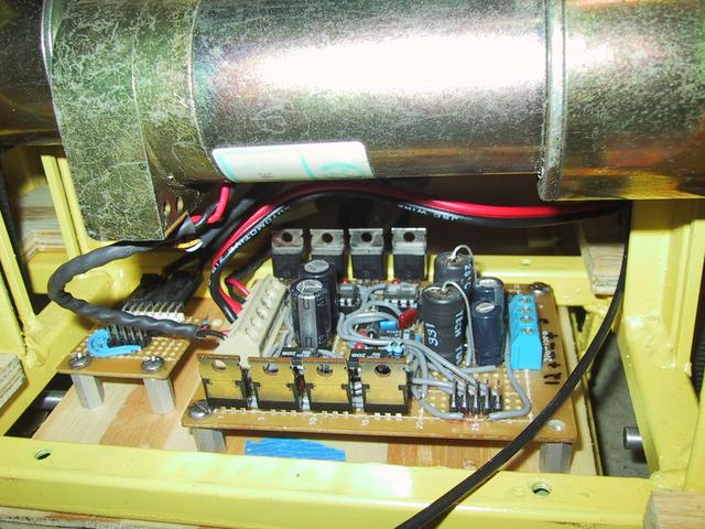
Motor drive board, mounted inconveniently below the motors. Each motor was driven by an H-bridge consisting of 4 fairly high-end N-MOSFETs. The drivers didn't have built in charge pumps, so those were added. In hindsight, giving the driver the ability to deliver full battery voltage to the motors continuosly might not have been such a great idea.
Aft main deck. This board was used to interface the main computer to the PWM generator (a CPLD), the quadrature decoders (LS7266 ASICs), and an ADC for the Infra-red sensor ring. These were accessed through a parallel port using an 8-bit address register for pseudo programmed-io with a 256 byte address space.
Forward main deck. This was the first sonar board I ever built and never really worked very well. It only had two channels installed out of the designed 8.
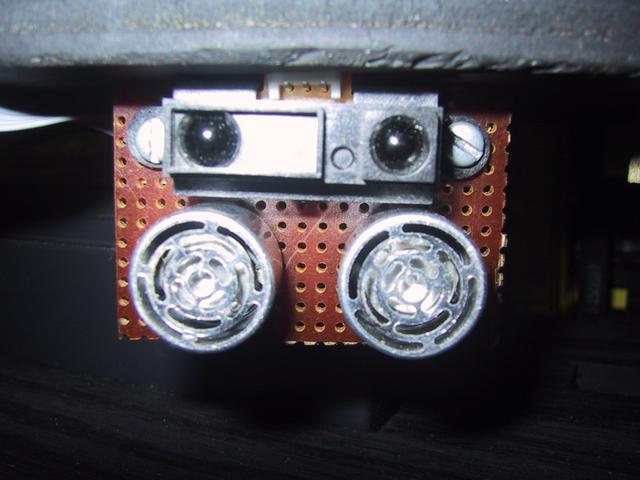
One of the combined GP2D12 / 40KHz sonar transducers.
GP2D12 ring.
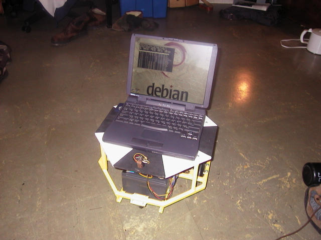
The first computer was a laptop sitting on top. (This was before the sensors were installed.)
The second computer installed was a VIA Mini-ITX, protected in a steel box. The disk drive was zip-tied under a few layers of industrial grade bubble-wrap.
Devilcat never had particularly clever software. It did have (while operating on a hard surface) spectacularly accurate dead reckoning, though. This was one of the maps from it.
Current Status
Retired due to profoundly misguided design choices.
© 2000-now
chris@jormungand.net