curl ⋅ lgr ⋅ devilcat2 ⋅ nemo ⋅ tiggerbot2 ⋅ logo ⋅ crunch ⋅ devilcat ⋅ tiggerbot
Curl


|
© 2010 chris@jormungand.net |
Mechanical/Drivetrain
 GIF DXF |
 GIF DXF |
The robot's main deck is made from compact discs and most of the drivetrain components are machined from black delrin thermoplastic. None of the parts require any particularly complicated operations to produce; however, basic machine tool skills are assumed and selection of proper tooling/setup/etc is left to the reader. All fasteners are plain-finish 18-8 stainless except for the standoffs which are aluminum.
Main Deck
 GIF |
 JPG |
 JPG |
Compact discs are made of thin polycarbonate and are somewhat difficult to work with; experimentation was required to achieve the desired results. One disc was deemed too weak for use as the deck; instead, two discs were laminated back-to-back using epoxy adhesive. To protect the surface finish during lamination the front faces of the discs were covered with vinyl tape; during machining the clamps and supports were wrapped in vinyl tape.
Gear Blocks
 GIF DXF |
 JPG |
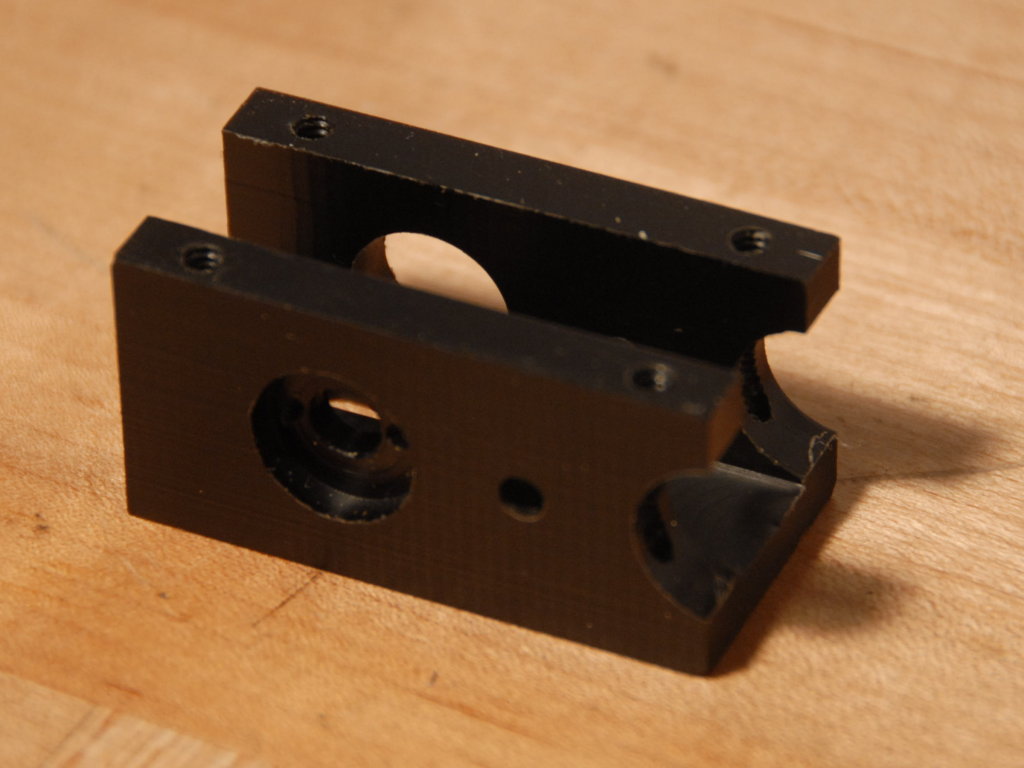 JPG |
Motors & Motor Gear Hubs
 JPG |
 GIF DXF |
 JPG |
 JPG |
Wheels & Wheel Hubs
 JPG |
 GIF DXF |
The wheel hubs are made of 1" round delrin. They have a bolt pattern matching what is added to the wheels and tapped for 4-40 NC. They are affixed to the 5/32" shaft with a radial 4-40 NC set screw.
Casters & Caster Dolly
 GIF DXF |
 JPG |
 JPG |
Electronics
Construction & Integration
The robot's electronic systems are constructed on three stacked boards. Each one is a RadioShack 4.5"x6.6" Grid-Style PC Board that has been cut to a 4.75" diameter circle. Each is attached to either the main deck or the next lower board by four 6-32 aluminum standoffs. Circuits are hand-soldered; power lines are wired with 22awg solid (i.e. proto-board) wire above the boards; data lines are wired with 30awg solid (i.e. wire-wrap) wire beneath the boards. Among the power lines, the color scheme is yellow/red/black/orange for 10v/5v/gnd/motor respectively.The boards are connected by a 10 conductor ribbon cable and rectangular insulation displacement connectors. The cable contains three ground conductors, two +5v conductors, and an I2C bus (SCL/SDA). I2C is a bus protocol supporting up to 127 devices and (in this application) 400 kbps bandwidth. Each board also has a standard AVR ICSP/ISP header, a reset button, and a pair of status LEDs.
| 2 SCL | 4 SDA | 6 | 8 | 10 |
| 1 GND | 3 GND | 5 GND | 7 +5V | 9 +5V |
| 2 VCC | 4 GND | 6 GND | 8 GND | 10 GND |
| 1 MOSI | 3 NC | 5 RST | 7 SCK | 9 MISO |
Battery & Drive/Power Board
 JPG |
 JPG |
The lowest board in the stack is closest to the battery pack and the motors and is the ideal place for all power handling and motor-drive related circuits. This is the board to which the battery pack connects. As such it contains the (single) fuse, the power switch, a current-sensing shunt, a charging jack, and the LM2675 switching regulator (rated for 1A output) which supplies the other boards with 5v power. It also contains one SN754410 driver for each motor. (Note that each chip is a quad half-bridge; drivers are doubled-up.) An atmega644 AVR on the board is responsible for controlling both drive motors; for each motor it monitors the two quadrature encoder outputs and controls its corresponding driver's PWM inputs. The AVR's analog-to-digital converter is used to monitor battery voltage and current.
| 2 NC | 4 +5V | 6 ENC B | 8 M- | 10 NC |
| 1 NC | 3 M+ | 5 ENC A | 7 GND | 9 NC |
The microcontroller on the drive board is responsible for motion control. It supports a wide range of commands over the I2C bus, from raw pwm control inputs to dead-reckoning based go-to-waypoint operations. It is also responsible for integrating all motions the robot has made since reset, thus providing an estimate of its position.
Sensor Board
 JPG |
 JPG |
The middle board in the stack contains the navigational sensors. There are two types of sensors: 40KHz ultrasonic sonars and infra-red parallax-type range finders. While each system measures distance to the nearest obstacle in several directions they have different qualities.
The sonar works by transmitting a burst of sound at 40KHz and waiting for an echo. Sonar is an ideal sensor for detecting obstacles: the beam pattern of the small transducers is wide and materials which do not produce sonar returns (especially at close range) are rare. Two transmit/receive pairs are mounted 3" apart each facing outward 20 degrees.
The infra-red range finder is a Sharp GP2Y3A002K0F. It operates by optical parallax: there are two lenses; with one, it projects an infra-red spot in a certain direction; with the other, which is offset slightly, it measures the angular position of the spot. Sharp makes a variety of these sensors; the relatively uncommon GP2Y3A002K0F has a range of 20-150 cm and has five separate LEDs, allowing it to measure the range in five directions with 5 degree spacing. As it is mounted, it measures the direction forward at angles of -10, -5, 0, +5, and +10 degrees.
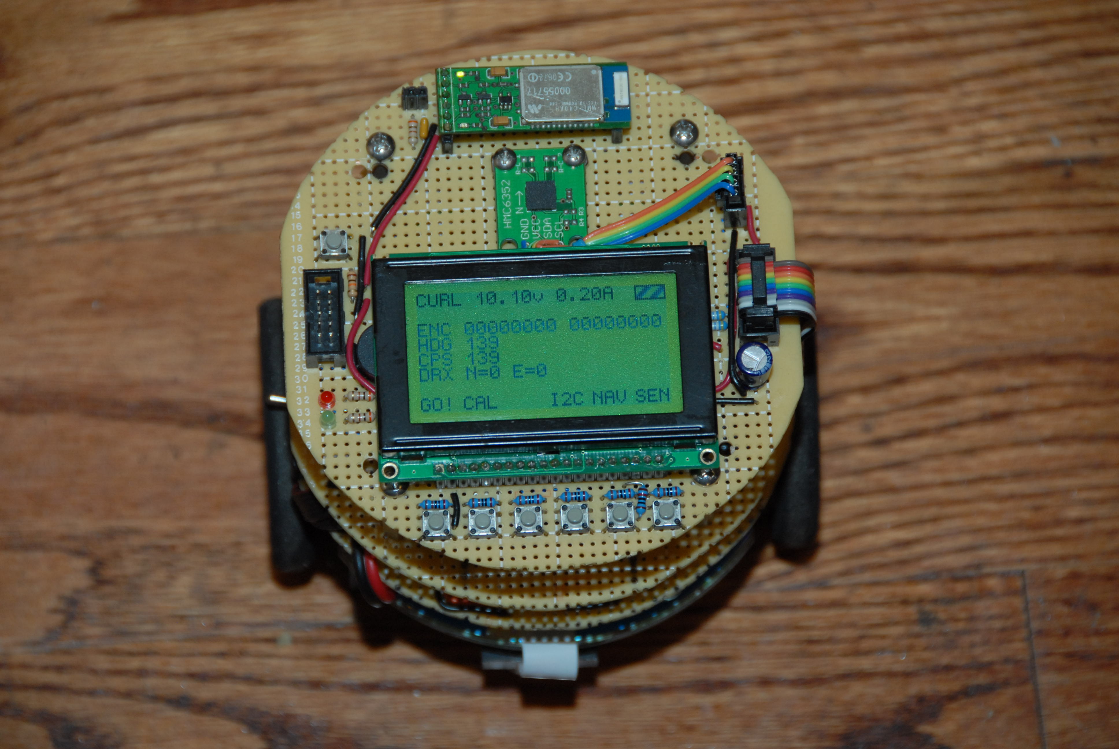
Control/Communication Board
 JPG |
 JPG |
There are no interesting circuits on the top board so no schematic is provided; the LCD connections are described in lcd.h. The menu buttons are 2k pulldowns on the LCD data lines; they can be read by setting the bus in a high-z state on both the LCD+AVR.
Software
Development Toolchain
The software for the three AVR microcontrollers is written in C. It was developed using the AVR port of the GNU GCC compiler. Code was uploaded using an Olimex STK500-compatible USB programmer and the AVRDude software package.Subsumption
The robot's control software is inspired by Rodney Brooks's "Subsumption" architecture. A good introduction to this can be found in AI Memo 864: A Robust Layered Control System for a Mobile Robot. In this system, control is decomposed into a set of modules which interact by sending messages to each other through specified channels. As defined by these channels, modules may inhibit other modules from sending messages; they may also suppress the inputs to other modules and replace them with other values. Suppression and inhibition have associated time constants which define how long before the effect wears off. The modules are typically divided into layers; lower layers implement simple behaviors directly, while higher layers implement complex behaviors, often by manipulating the lower layers via inhibition and suppression.N.B. subsumption is often described as simply a prioritized list of behaviors, all of them accessing raw sensor data, and an arbitrator that simply chooses the highest priority active behavior. This is a simplified subset of the general system.
Implementation
The implementation presented in Brooks's paper was written in LISP and ran on offboard systems linked to the robot via radio. The implementation in this robot is written in C, with the obvious implications in programming style. Brooks defined each module as a state machine and defined a very specific set of legal state transitions. In our case, each module's logic is implemented in a function that is free to carry out any combination of outputs, side-effects, etc.Example
In this simple example, the robot will drive forward until it nears an obstacle, at which point it will turn in place until it has a free path forward. First, we define four modules:The first module, sonar, periodically retrieves measurements from the robot's two sonar sensors. The last module, motor, sends commands to the robot's drive system. forward always attempt to drive the robot forward, while near turns the robot when an obstacle is present. These behaviors are implemented as follows:SS_MODULE(sonar) SS_OUTPUT(dist, struct ss_range) SS_ENDMODULE SS_MODULE(forward) SS_OUTPUT(cmd, struct ss_drive) SS_ENDMODULE SS_MODULE(near) SS_INPUT(dist, struct ss_range) SS_OUTPUT(cmd, struct ss_drive) SS_ENDMODULE SS_MODULE(motor) SS_INPUT(cmd, struct ss_drive) SS_ENDMODULE
SS_FUNCTION(sonar)
  struct ss_range s;
  s.left  = read_sonar_left();
  s.right = read_sonar_right();
  SS_SEND(dist, s);
SS_ENDFUNCTION

SS_FUNCTION(near)
  if (SS_HAS(dist)) {
    if (SS_IN(dist).left < 12 || SS_IN(dist).right < 12) {
      struct ss_drive turn;
      turn.left = 40;
      turn.right = -40;
      SS_SEND(cmd, turn);
    }
  }
SS_ENDFUNCTION

SS_FUNCTION(forward)
  struct ss_drive fwd;
  fwd.left = 40;
  fwd.right = 40;
  SS_SEND(cmd, fwd);
SS_ENDFUNCTION

SS_FUNCTION(motor)
  if (SS_HAS(cmd)) {
    motor_set(SS_IN(cmd).left, SS_IN(cmd).right);
  }
SS_ENDFUNCTION
The first four statements create the modules; the DEFWIRE statements link them together. The forward module is connected to the motor module. The sonar module sends its readings to the near module which is connected to suppress the command input of motor; if an obstacle is too close, the near module will tell the motors to turn and also suppress any inputs from forward for a period of 5 ticks. (0.5s)ss_sonar_t sonar = ss_sonar_create(); ss_motor_t motor = ss_motor_create(); ss_forward_t forward = ss_forward_create(); ss_near_t near = ss_close_create(); SS_DEFWIRE (forward, cmd, motor, cmd ); SS_DEFWIRE (sonar, dist, near, dist ); SS_DEFWIRE_SUP(near, cmd, motor, cmd, 5);
SS_* are C preprocessor macros; combined, they have the effect of distributing outputs from modules to the inputs of whatever modules are specified via SS_DEFWIRE* and implementing timing logic as required.
Results
 PNG |
 JPG |
 JPG |
It is well known that all robots see the world in red with a white metadata overlay. Curl has no native video capability so it had to be recorded with a camera strapped on top. Curl does have a telemetry transmitter, though. An LED controlled by the top microcontroller blinks every 10s according to the same clock used to timestamp logging events; this allows the log and video to later be synchronized. (Unfortunately, the compass is basically random during the video due to the poor selection of an iron counterweight for the camera.)
Other Code
There is obviously much more code for mundane tasks such as copying data between the microcontrollers, counting quadrature encoder ticks and sonar responses, etc. It is about 3600 lines total and is available here. It is, clearly, a work-in-progress; use at your own peril. Note that this contains some code from FreeRTOS which is used on the top board AVR.Parts
 JPG |
 JPG |
| Description | Source | Qty | Unit |
| COMPACT DISC | 1990s | 2 | |
| NiMH 9.6v 2200mAh Battery Pack | BatterySpace.com | 1 | |
| 2N2222 NPN Transistor | DigiKey | 1 | |
| Cable, Ribbon, 10-conductor, 0.05", Rainbow | DigiKey | 6 | inch |
| CAP 0.1 uF Ceramic | DigiKey | ?? | |
| CAP 330 uF Aluminum | DigiKey | ?? | |
| DIODE SR06 | DigiKey | 2 | |
| DIODE ZENER 15V 1A | DigiKey | 1 | |
| Fuse 1A | DigiKey | 1 | |
| Fuse Holder | DigiKey | 1 | |
| Header 2x10 Keyed | DigiKey | 9 | |
| IC ANALOG MUX CD4052 | DigiKey | 1 | |
| IC BRIDGE SN754410 | DigiKey | 2 | |
| IC DIGPOT AD5220 | DigiKey | 1 | |
| IC DRIVER MIC4427 | DigiKey | 2 | |
| IC LM2675 Simple Switcher 5V 1A | DigiKey | 1 | |
| IC LOGIC 74HCT08 QUAD AND | DigiKey | 1 | |
| IC MCU ATMEGA1284P | DigiKey | 1 | |
| IC MCU ATMEGA644 | DigiKey | 2 | |
| IC OPAMP LM324 | DigiKey | 2 | |
| INDUCTOR 1.2uH | DigiKey | 1 | |
| INDUCTOR 15uH CHOKE | DigiKey | 3 | |
| INDUCTOR 375 uH POWER TOROID | DigiKey | 3 | |
| INDUCTOR 53 uH POWER TOROID | DigiKey | 1 | |
| LED 3mm Green | DigiKey | 3 | |
| LED 3mm Red | DigiKey | 3 | |
| RESISTOR 0.01 Current Sense | DigiKey | 1 | |
| RESISTOR 1/4W various | DigiKey | ?? | |
| SENSOR, SHARP IR GP2Y3A002K0F | DigiKey | 1 | |
| Standoff Aluminum 6-32 Hex 0.625" M-F | DigiKey | 12 | |
| Standoff Aluminum 6-32 Hex 0.75" F-F | DigiKey | 4 | |
| SWITCH, TACTILE | DigiKey | 9 | |
| Terminal Block, Screw, 2-pos 0.2" | DigiKey | 1 | |
| Wire, 22 AWG Solid (proto board type) (various colors) | DigiKey | ?? | |
| Wire, 28 AWG Solid (wire wrap) | DigiKey | ?? | |
| XTAL 20Mhz | DigiKey | 3 | |
| DC MOTOR, MAXON 13MM | Ebay | 2 | |
| ALUMINUM, ROUND, 0.50" DIA | McMasterCarr | 1 | inch |
| DELRIN, BAR, 1"x1" | McMasterCarr | 9 | inch |
| DELRIN, ROUND, 1" DIA | McMasterCarr | 1 | inch |
| MACHINE SCREW, 4-40 PH 3/8" | McMasterCarr | 10 | |
| MACHINE SCREW, 6-32 PH 5/16" | McMasterCarr | 18 | |
| MACHINE SCREW, M2 x 5MM PH | McMasterCarr | 4 | |
| SHAFT, 0.156" DIA | McMasterCarr | 5 | inch |
| CASTER, BALL, 1" PLASTIC | Pololu | 2 | |
| General Purpose PC Board 4x6 | RadioShack | 3 | |
| GEAR, ACETAL SPUR, 32P 14T | SmallParts | 2 | |
| GEAR, ACETAL SPUR, 32P 28T | SmallParts | 2 | |
| LCD 128x64 | SparkFun | 1 | |
| Module BlueSMIRF Sparkfun | SparkFun | 1 | |
| Module Compass HMC6352 Sparkfun | SparkFun | 1 | |
| WHEELS, 2.5" DUBRO MICRO-SPORT | TowerHobbies | 2 | |
| CABLE TIES, SMALL | 4 | ||
| Connector, Deans Ultra Plug, F | 1 | ||
| Connector, Deans Ultra Plug, M | 1 | ||
| EPOXY 30M |
© 2000-now
chris@jormungand.net